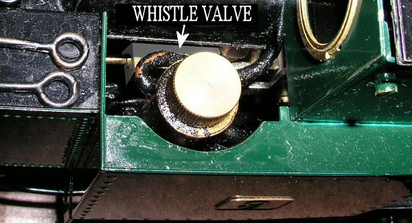
FIG 1. Location of the whistle valve.
On the Rheidol models fitted with a working steam whistle, it is important to lubricate the whistle valve regularly to prevent it from sticking. This is particularly important if the model is not going to be used for some time i.e. before a winter lay-up. The valve is situated in the left hand cab side tank, between the displacement lubricator and the boiler - see Fig1.
FIG 1. Location of the whistle valve.
To lubricate, proceed as follows.
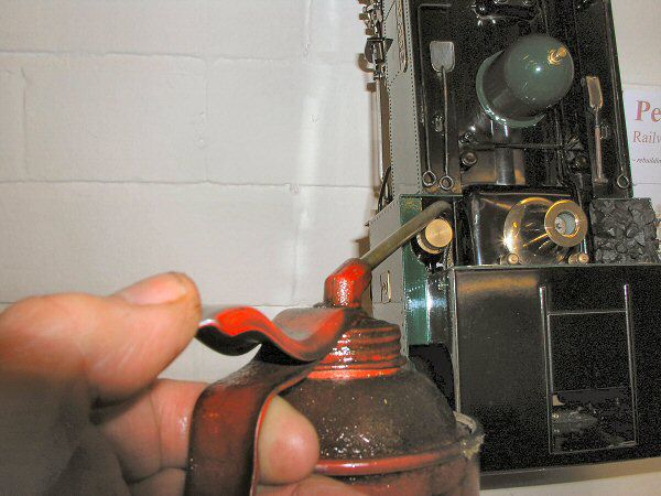
FIG 2. Position for lubrication.
If the valve should become stuck, proceed as follows.
Remove the dummy coal loads, brass dome and safety valve bonnet.
Remove the left hand side tank. This fixed by a single screw under the front foot plate between the front of the cylinder and the front, side step. Remove this screw and slide the side tank forward a little until the two tabs on its rear edge, disengage the slots on the front of the cab side tank. Now carefully lift the tank off so that the three tabs at the top disengage the slots on the boiler cover plate. Note that there is a large brass weight in the front of the tank and which must be held in place as the tank is removed or it may fall out and damage the model.
Repeat for the right hand side tank.
Lift up the cab roof and disconnect the ariel wire where it clips to the underside of the roof. On models fitted with the 2.4GHz r/c system, this does not apply.
Carefully, lay the model on it's side and remove two brass cheesehead screws (marked A in Fig 3) that hold the rear of the cab to the foot plate. These ate situated just in front of the rear buffer beam and to the outside of the frames.
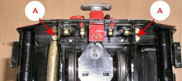
FIG 3. Rear cab fixing screws.
Stand the loco on it's wheels again and remove the two screws and nuts (one each side) that attach the front of the cab side tanks to the inner foot plate, marked A in fig 4.
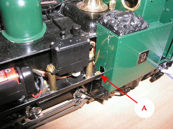
FIG 4. Front cab fixing screws.
Now the cab can be carefully lifted off.
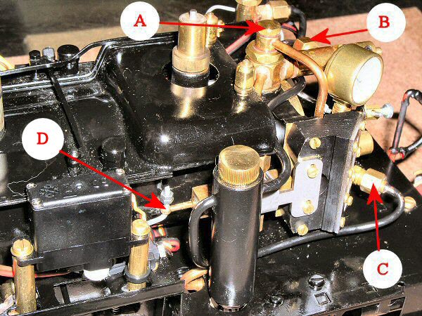
FIG 5. Cab and tanks removed.
Sometimes, a gentle tap on the front end of the piston extension (marked D in fig 5) will free the stuck piston, so try this first. You will need a long thin rod to get in from the front of the loco and down the back of the whistle valve servo. Lifting the battery pack out of the way will allow you place the rod on the end of the piston extension. If the piston will then move, lubricate as detailed above then re-fit the cab and tanks.
If it is still stuck, the valve will require removing as follows.
Remove the pressure gauge by unscrewing the top banjo bolt marked A in Fig 5.
Unscrew union nuts B and C in Fig 5, remove the lubricator drain screw then carefully remove the lubricator. The copper pipes thread their way around the water gauge and steam regulator but the whole unit will come off without bending the pipe.
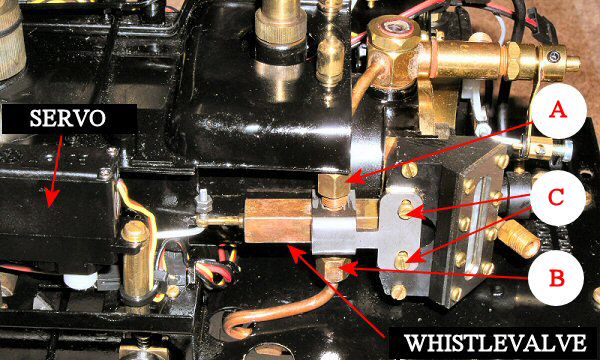
FIG 6. Removing the whistle valve.
Referring to Fig 6, remove the two screws marked C that fasten the whistle valve bracket to the water gauge.
Unscrew union nuts A and B to release the whistle valve. Note that once Union nut B is unscrewed, the whistle will be free to move about under the foot plate.
Now switch on the r/c transmitter and receiver and set the whistle to the closed position - control stick to the bottom. Note the position of the servo arm to allow you to re-fit it in the correct position later.
Lay the loco on it's right hand side and, using a small Phillips head screwdriver, remove the small screw that fastens the servo horn to the underside of the servo. Next, gently prise the horn off the shaft. Note that the shaft and horn are splined to aid re-positioning.
The whistle valve can now be lifted off the engine.
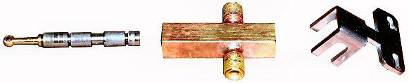
FIG 7. Whistle valve components.
The servo horn and linkage do not need removing from the piston.
Carefully tap the piston out of the body using a soft punch or piece of brass bar.
Clean the parts with thinners and dry.
Lubricate with a little steam oil and try the piston back in the body. It should slide smoothly in and out of the body with no tight spots. As it is normally lime scale that causes the valve to stick, it should fit back correctly once cleaned and oiled. If, however you can feel and tight spots, it may be that the piston or bore has been slightly damaged. This can normally be polished out using a little 'Brasso', 'T cut' or similar polish. To do this, clean the piston and body and apply a small amount of the preferred compound to the piston and work it in and out of the body, rotating it as you do so. Keep doing this for a few minutes then wash off all traces of the compound, apply oil and check the fit. Once you are happy that you have a nice smooth operation, re-fit the valve.
Place the valve back in position on the loco and screw on union nuts B and C finger tight.
Re-fit the whistle valve bracket with the two screws through the water gauge.
Switch on the r/c, set the whistle control stick to closed and refit the servo horn in the same position as it came off.
Tighten the union nuts B and C and check operation of the valve by radio control. The piston should move in and out smoothly and the front of the piston extension should not hit the edge of the inner bodywork that is just behind it. To check that you have it in the correct position, when in the closed position, the front of the steel piston (not the brass extension) should be flush with the end of the valve body. As the valve is opened, the piston is pushed into the valve body.
Once this is set correctly, the servo horn retaining screw can be re-fitted.
Carefully thread the pipes of the lubricator back round the water gauge and steam regulator and re-connect unions B and C in Fig 5.
Refit the pressure gauge, not forgetting the two small fibre washers that go, one either side of the banjo. Nip-up but do not over tighten the brass banjo bolt.
It is wise, to give the loco a steam test at this stage, to ensure that all is working correctly and there are no steam leaks.
If all is well, re fit the cab - two screws from under the foot plate at the rear and two screws and nuts at the front - not forgetting to pass the ariel wire up to the roof and re-connect it.
Re-fit the side tanks, taking care that all five locating tabs (two at the rear, three on the top) are located correctly in their respective slots and that the weight is in place at the front. The front fixing screws fasten into these blocks and hold both tank and weight in place.
Roundhouse Engineering Co. Ltd., Doncaster, UK. 2018. Click Here To Return To The Homepage