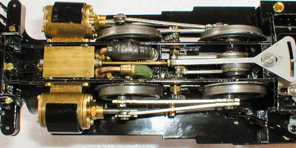
FIG 1. Underside of 32mm gauge Forney showing original style silicone pipes. Note the reinforcing wire spring around the steam supply pipe.
The original version of the Forney locomotive was fitted with flexible steam and exhaust pipes made from silicone rubber. These proved to be prone to splitting, despite being fitted with a reinforcing stainless steel spring wrapper over the steam supply pipe. To overcome this, later models were fitted with PTFE pipes which have no such weakness and, being much smaller in diameter, allow more clearance on the 32mm gauge models.
We can no longer supply the original silicone pipes but instead, recommend conversion to the later and far superior PTFE type. This document describes the conversion process for those wishing to carry out the work themselves. The model used in this exercise is a 32mm gauge version but the process is the same for either gauge.
We can supply the replacement flexible pipes, ready made to length with threaded ends fitted and also new fibre washers for the banjo bolts.
You will also need a small (junior) hacksaw, 4BA open ended spanner, 4BA thread die, pliers and liquid thread sealer.
FIG 1. Underside of 32mm gauge Forney showing original style silicone pipes. Note the reinforcing wire spring around the steam supply pipe.
The first job is to remove the power bogie from the loco.
Start by disconnecting the reversing linkage. This is a laser cut stainless quadrant that pushes the reversing piston. It is held in place by a short crank pin and washer which screws into the rear frame spacer. Do not remove the reverser/piston assembly completely, but leave in place. Removing the crank pin allows the reverser linkage to be rotated out of the way in later steps. FIG 2 shows the crank pin being removed with a 6BA nut spinner.
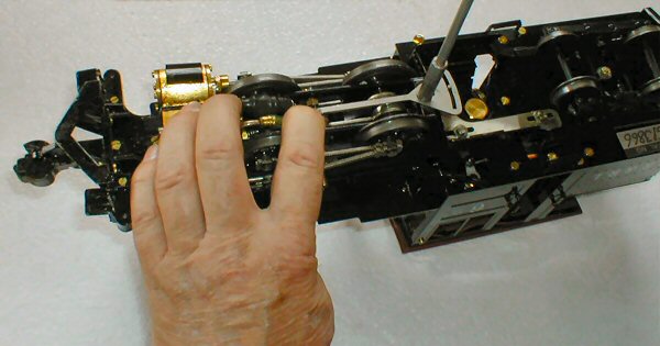
FIG 2. Disconnecting reverser.
Next, disconnect the steam and exhaust pipes from the reversing block. These connect to the rear of the block by two banjo bolts which are unscrewed using a screw driver as shown in FIG 3. In the picture, the steam supply pipe is the upper one with the stainless steel spring around it and the exhaust pipe is the lower one. Each banjo bolt has two small fibre washers.
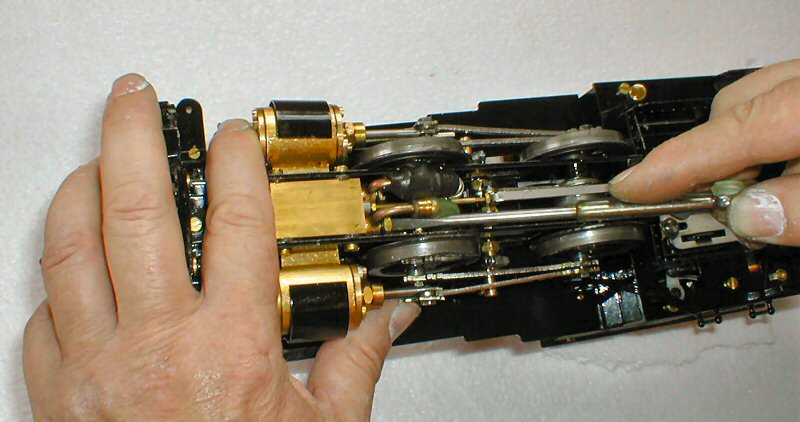
FIG 3. Disconnecting the steam and exhaust pipes.
The pivot for the power bogie is in the center, between the eccentric rods. The previously disconnected reversing linkage can be rotated to allow access to the pivot nut with a 6BA nut spinner as shown in FIG 4. Remove the nut and washer then lift the power bogie off the engine , threading the flexible steam and exhaust pipes through the chassis as you do so.
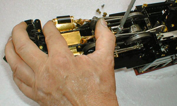
FIG 4. Removing the power bogie pivot.
With the power bogie removed, you will see that the two flexible pipes are attached to metal pipes that are clamped into the base of the smokebox, FIG 5.
The exhaust pipe must be removed completely. Slacken the smokebox clamp screw just behind the steam pipe, as shown in FIG 5. This will allow the base of the smokebox to open slightly so that you can slide the exhaust pipe forwards out of it's clip (see FIG 6). It may be necessary to bend the two half's of the smokebox base that form the clip, in order to free the pipe. Note that there is a brass collar with a groove round it, soldered to the copper exhaust pipe, and it is this collar that actually fits in the clip.
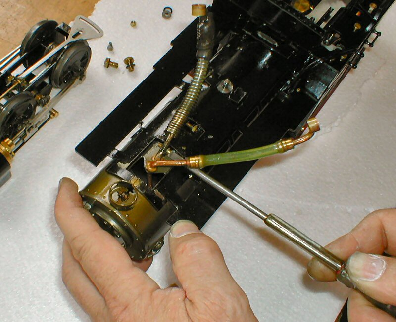
FIG 5. Slackening the smokebox clamp screw.

FIG 6. Exhaust pipe being removed from split clamp.
The stainless pipe from the superheater must now be modified to take the new PTFE flexible pipes. FIG 7 shows the underside of the smokebox with the main steam pipe still held by the rear part of the split clamp. The old silicone tube and brass ferrule has been removed (this can simply be cut off with a sharp knife) and the brass collar soldered to the end of the steam pipe is clearly visible. This collar must be removed by sawing off the end of the tube just behind the collar.
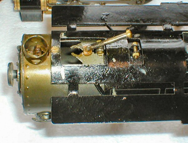
FIG 7. Main steam pipe with old flexible pipe removed.
FIG 8 shows the collar being removed. The steam pipe has been carefully bent upwards a little to allow a small wooden block to be placed under the pipe to support it. Grip the pipe with a pair of pliers and, using a junior hacksaw, cut through carefully just behind the collar.
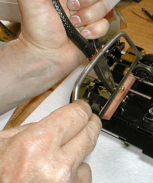
FIG 8. Cutting the end off the steam pipe.
Now, the end of the pipe must be threaded 4BA for approx. 3 to 4mm in length. FIG 9 shows this being done with a small, hand die holder and FIG 10 shows the completed task.
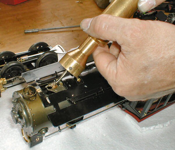
FIG 9. Threading steam pipe.
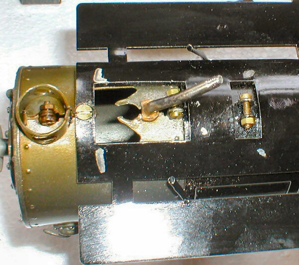
FIG 10. Finished steam pipe.
The copper exhaust pipe should now be similarly modified after removing the old silicone tube. As before, saw off the end of the pipe just behind the collar but this time, as the exhaust pipe is not attached to the loco, it can be held in a vice. Thread the end 4BA for about 3 to 4 mm.
The two banjo connectors with the short, bent, copper pipes attached should also be modified in the same way. FIG's 11 and 12 show them being cut and threaded in the vice.
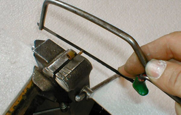
FIG 11. Cutting the end off the copper pipe.
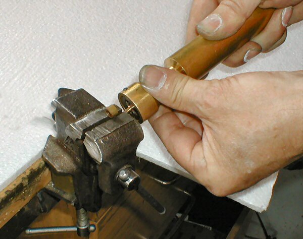
FIG 12. Threading the end off the copper pipe.
You now have a set of modified metal pipes to go with the new PTFE flexible pipes.
FIG 13 shows the set of pipes ready for fitting. Note that the new PTFE flexible pipes are supplied ready made with the brass ends crimped on, ready to screw onto your modified pipes.
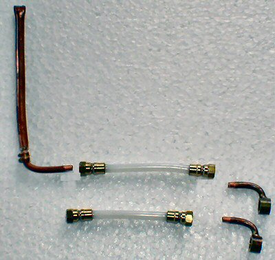
FIG 13. the completed set of pipes ready for fitting.
Carefully bend the stainless steam supply pipe back into position. The copper exhaust pipe can now be replaced in the smokebox and positioned as shown in FIG 14, laying next to the stainless steam supply pipe. Ensure that the brass collar on the exhaust pipe fits into the split clamp in the base of the smokebox and bend the clamp back into position before tightening the smokebox clamp screw to hold both pipes in position.
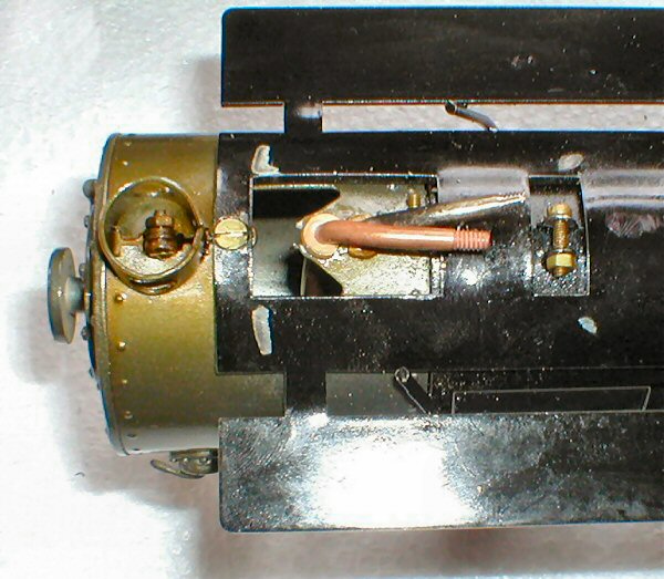
FIG 14. Exhaust pipe replaced and clamped into position next to steam supply pipe.
Now the new flexible pipes can be fitted. These have a female threaded fitting at each end which screws onto the threads that you have formed on the modified pipes. Use a spot of liquid thread sealer as you screw them on and nip up tight using a 4BA spanner. The banjo fittings should both be pointing upwards as shown in the photo. Note that the flexible exhaust pipe is slightly longer than the flexible steam supply pipe.
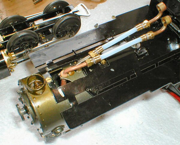
FIG 15. New pipes fitted.
The power bogie can now be re-fitted, threading the two flexible pipes up between the front axle and center frame stretcher as you lower the bogie onto the pivot pin. Replace the washer and nut on the pivot pin and nip-up with a 6BA nut spinner.
Re-connect the flexible pipes to the reversing block with the banjo fittings - FIG 16 shows the steam supply pipe connected and the exhaust pipe all ready to bend over and connect. Don't forget to fit a new fibre washer on either side of the banjo ring. Note that on the underside of the reversing block, there are two marks stamped on the rear edge adjacent to the banjo connections. I marks the inlet side and X marks the exhaust side. Do not get the two pipes crossed over or the model will not work correctly.
Ensure that the copper pipes from the banjo bolts are correctly positioned so that they do not interfere with the reversing piston that must be free to travel in and out of the reversing block.
Check that the power bogie can pivot freely and the pipes do not foul or jam on any of the valve gear. It may be necessary to adjust the position of the banjo fittings and/or bend any of the modified pipes slightly to achieve a good alignment.
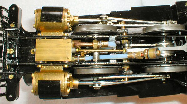
FIG16. Re-connecting the pipes.
Finally, re-fit the reversing linkage by fitting the short crank pin with washer through the longitudinal slot and ensuring that the curved slot in the rear end, fits over the peg on the slider under the cab floor.
Roundhouse Engineering Co. Ltd., Doncaster, UK. 2018. Click Here To Return To The Homepage