This describes the procedure for adjusting the slide valves on the simplified Walschaerts valve gear as fitted to certain Roundhouse locomotives, so that they open and close at the correct time.
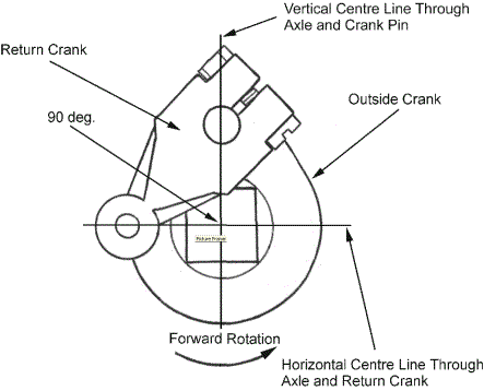
It assumes that the return cranks have not been disturbed, as these are drilled and pinned during construction so that they do not move from their optimum position of 90 degrees in advance of the drive crank pin.
Carefully remove the valve chest covers from the cylinders, and replace two screws in each to hold them in position.
Set the valve gear to mid position and look down into the valve-chests and note the position of the slide valves. They should be sitting centrally over the steam inlet ports, covering both. If they are not, disconnect the radius rod from the valve spindle fork end and rotate the valve spindle to screw the slide valve in the desired direction.
Re-connect the radius rod and re-check position. There may be a small amount of fore and aft free movement of the valve if the spindle is moved with the fingers, which just uncovers the steam ports. If this is the case, adjust the valve position so that the ports are opened an equal amount when moved thus. Repeat this with both sides until the valves are correctly positioned.
Set the gear for forward running, with the radius rods lowered in the expansion links.
They should be positioned near, but not right at the bottom of the expansion link. The gear is now set for forward running so, rotate the wheels by hand in a forward direction and watch the slide valve movement.
The edge of the steam ports should become visible (crack open) as the crank pin on the drive axle is at dead center. The front steam port should be cracking open at front dead center and the rear steam port at rear dead center.
Any adjustment is achieved by disconnecting the radius rod from the valve spindle and rotating half a turn at a time as described above.
As an example, if the front port is opening when the crank pin is before front dead center (too early) and the rear port is opening when the crank pin is after rear dead center (too late), then the slide valve should be moved forwards on the valve spindle. This will force it to open the front port a little later and the rear port a little earlier and is achieved by rotating the valve spindle anti-clockwise.
Set the gear for reverse running, with the radius rods near, but not right at the top of the expansion links and rotate the wheels in the reverse direction.
As before, the edge of the steam ports should become visible (crack open) as the crank pin on the drive axle is at dead center. The front steam port should be cracking open at front dead center and the rear steam port at rear dead center.
The idea is to get as equal a balance as possible between the port openings when the drive crank pins are at either front or rear dead center s in either forward or reverse running direction.
The actual valve opening position will vary depending on how worn the valve gear is. The more wear in the linkage, the later the opening will become, so don't worry if you are unable to achieve port 'cracking' at exactly crank pin dead center. What is more important is that it should be balanced i.e. 2 degrees after dead center for all openings.
If it is not possible to achieve roughly balanced port openings, it could be due to other problems in the valve gear as follows.

This should lead the drive crank pin by 90 degrees in the forward direction of rotation.

There are three different lengths of eccentric rod used on Roundhouse models with lengths of 74.01 mm, 67.11 mm and 42.02 mm between hole centers. Distance should be measured as in diagram.

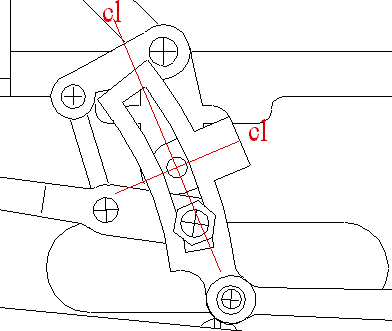
The center of the curved slot on the expansion link, must coincide precisely with the center of the pivot to which it is attached. If it does not, the arc described by the top half will not be a mirror of that described by the bottom half.
Once you are happy with the visual settings, the valve chests can be closed ready for a steam test.
Squirt a little steam oil into the valve chest as you replace the top cover and gasket, to help lubricate and seal the valve. Note that the valve nut has a flat machined on it, which must be to the bottom when sitting it down into the slide-valve. If it is not, the valve spindle will lock up and may be damaged when the valve chest cover screws are tightened.
When the locomotive is capable of running on the track under its own steam, the timing can be fine-tuned for best performance.
Set the loco off on a reasonably level length of track at a slow speed. If it stalls, note the position of the drive crank pins and if either is at front or rear dead center. Repeat this several times and it will soon show up if there is a 'dead spot' at any particular point of the valve cycle. If, for instance, it keeps stalling with one particular crank pin just after rear dead center, then this would indicate that the slide valve is opening a little late. Disconnect the radius rod on that side and rotate the valve spindle half a turn to move the slide valve forward a fraction as detailed in valve timing earlier. Reconnect the radius rod and try the loco again in both directions to check that your adjustment has not simply removed that dead spot only to replace it one in a different position. A short time spent running the engine and making adjustments of just half a turn of the valve spindle at a time should soon show its optimum positions.
Roundhouse Engineering Co. Ltd., Doncaster, UK. 2018. Click Here To Return To The Homepage